|
Written/Photography by Albert V
Recently I found myself at the Super Crawl. You may have followed along with the pictures last issue. I had a bit of time on my hands so I started having a look at what makes up a rock crawl buggy. As you well know these machines are far removed from what you and I use on the trail, but if someone else has tried something these would be “the guys” to borrow ideas from. In their quest for an unbreakable machine that can turn in its own wheelbase, there were some cool steering and axle set ups to be found. I took a few shots so maybe you can glean something from them for your own use – I know I already have...
We will start simple. This is a typical one-ended ram system. A single ram attaches to a tie rod. Push fluid into the ram one way, the ram moves one way – push fluid into the ram the other way, it moves the other way. The only problem is fluid displacement. Because in one side of the ram there is a shaft and the other side nothing – it will take less fluid to push the ram in than out, a system well suited for rear steer.
This is a typical ram-assist set up. A tie rod goes from wheel to wheel, and a drag link attaches the steering box to the passenger side knuckle. As full hydraulic is not allowed in some competition classes, this is the next perfect way to keep your truck legal (street legal too) and still benefit from added power from a steering ram. The cool things here are all the aluminum rods and how perfectly flat the driver got all the bars – even the track bar on the raised bracket. This eliminates bump steer almost completely.
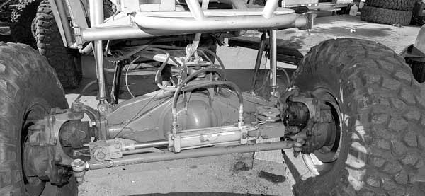 While technically this is just a typical, single-ended ram rear steer set up, check out that axle. While being kind of ugly, it is actually a hybrid Ford 9-inch Unimog Portal. Not sure with an axle that narrow what purpose the truss serves but it sure makes it look huge.
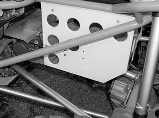 This set up is pretty cool. Look closely, most four-links use two longer arms on the bottom in a V pointing backwards (narrow at the front wide at the back). Two arms on the top point forwards in a tight V. This one is backwards. Now have a look at the winch rope. When drivers use air shocks they need to control the axle during descents, as the shocks tend to unload. Even though that’s not a big deal these days, the winch line goes through a pulley and inside the tube attached to the top of the diff. The winch is under the back of the driver’s seat. The rear steer also uses a double-ended ram, which also acts as the tie rod. This provides better steering control as the fluid displacement is the same on both sides of the ram.
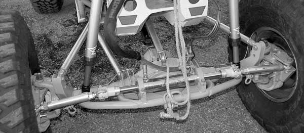
To attach the ram to the tie rods, most owners seem to use Hiem ends. Cheap, easy and they articulate well. Most of the rams used a link like the one above. It screws into the end of the shaft. One vehicle I saw went the other way. Same thing, just different.
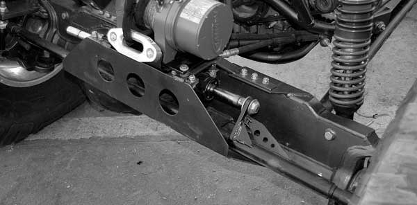
Here is the full steering set up shown above. Very nicely done. This is the front full hydraulic steering. The hoses run up the centre control arm to the ram. As a 9-inch axle was used there is no worry about covering up a diff cover with the ram. Hi steer arms keep everything up nice and high while the ram cradle has a tow point on it too. Like the other four link the upper arms are longer while a single arm flares out acting as a skid plate under the engine. (It has an aluminum insert in it to slide on rocks).
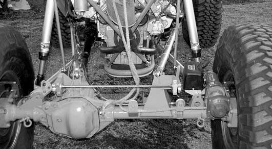
This isn’t such a big whoop but a few things are cool. It is the more typical short arm top, long arm bottom, four-link rear. Nice use of the anti-rock style sway bar. Check out the elaborate pulley system for the rear axle winch. The winch is mounted on the axle to reduce sprung weight. The rope runs through two pulleys on the axle up to another pulley on the tube chassis then back down to the axle.
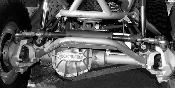
This buggy had the nicest, cleanest hydraulic steering of them all. Built (and owned) by Trail Tough, the front steer features a double-ended ram on a removable cradle (access to diff cover this way). Notice the bushings on the ends of the tube near the knuckles. The ram sits in a V of tube which then bolts to the top of the Rock Crusher housing (it has provisions for six bolts on top to attach stuff). There is a bump stop, which rests on the tube right behind the ram to control up travel. Also check out the rubber bands on each side behind the ram. Rather than an anti rock bar or a winch to help control the air shocks, those over sized bungee cords do the trick!
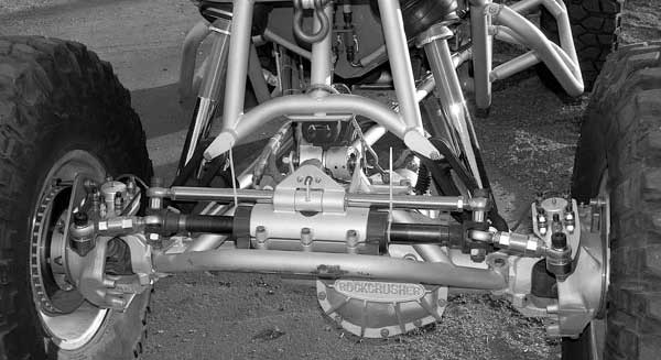 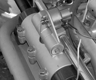 This is the rear steer on the same Trail Tough rig. Again bushings, V-saddle and bolts to the top of the housing. Those bungee cords are there too. However, this ram is in a bolt-together sleeve to hold it in place while the front ram was welded in place. The trick thing here is that chrome bar above the ram. The chrome bar has a notch cut in it to facilitate a centre lock-out mechanism. An electric solenoid (at right) controls a steel block that drops into the notch to hold the steering straight. You can also just get a peek at the air bags on top of the shocks.
And lastly, a good idea with not enough thought. I first saw this and thought, yeah – that’s a good idea...mostly because I don’t like Hiems (I prefer ball joints) for mud and snow. Mount the ram and just drop brackets to the tie rod. The problem here is that the tie rod moves too much and without making the ram pivot so it can rock when the tie rod gets closer to the axle under full turn, it can’t work. Notice how one end is not attached? This guy found that out too.
|
