
This Quanta LB6M is everywhere, yet you won’t find it on Quanta’s website. That’s because it’s not sold to end users, it is an early hyper-scale switch based on the Scorpion chipset. It’s the first 10 GBit/s merchant silicon chipset used by Google and probably others in the development of their large-scale networks, most famously illustrated by the Pluto Switch. The history of the Google network is a Must Read.
According to Metcalfe’s law, the value of the network is proportional to the square of the number of connected users. With squared values in mind, check out this config with several 10 GBit/s Intel X520-DA2 & Mellanox ConnectX-2 MNPH29C-XTR NICs, and the Quanta LB6M, which came new from UNIXPlus. The cabling I use is a 3m Active Optical Cable, the AVAGO AFBR-2CAR03Z.
We previously covered the LB6M in Turbocharge the Quanta LB6M with Brocade TurboIron which focused on using a different OS. This article looks at using the standard OS with the switch.
Table of Contents
Here is what we are going to cover in this article:
The Switch
Here’s the version information of this switch derived from the command show version.
System Description............................. Quanta LB6M, 1.2.0.18, Linux
                                                2.6.21.7
Machine Type................................... Quanta LB6M
Machine Model.................................. LB6M
Serial Number.................................. QTFCRW6030118
FRU Number..................................... 1LB6BZZ0STJ
Part Number.................................... BCM56820
Maintenance Level.............................. A
Manufacturer................................... 0xbc00
Burned In MAC Address.......................... 54:AB:3A:42:0B:40
Software Version............................... 1.2.0.18
Operating System............................... Linux 2.6.21.7
Network Processing Device...................... BCM56820_B0
Additional Packages............................ FASTPATH QOS
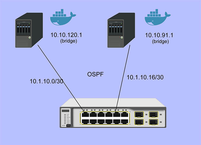
There are 24 SFP+ ports on the Quanta LB6M as well as a two copper Gigabit ports and two management ports. The FASTPATH software on the LB6M also supports OSPF, which distribute Layer 3 routes dynamically as devices are added and subtracted from the network. In this article, I will show how OSPF can be used for container style networking.
My primary use case for using OSPF is to allow containers to connect to other containers through virtual bridges defined on each host. Each virtual bridge defines a network and OSPF configures the routes for these networks. Without dynamic configuration, I would need to define static routes on each host for every other host — this would become unmanageable very quickly. Protocols such as Docker Swarm also enable dynamic configuration through other mechanisms, but the scope is limited to containers controlled by Docker.
Installation
The serial port on the LB6M defaults to 9600-N-1, no flow control. The blue Cisco style cable works well, but my switch did not include this. It will also use DHCP to configure the management port, so you can use telnet to connect to it initially by setting up dhcpd and serving an address to the switch.
The configuration language used is a version of LVL7 FASTPATH, which is a NOS that is now a part of Broadcom. The examples here contain FASTPATH prompts that signify the mode of configuration the switch is in. They are described here: The FASTPATH Configuration Modes.
Enabling ssh and Disabling telnet
The first configuration item I did was setting up ssh and ntp. While telnet works, ssh is secure and ubiquitous.
- Set the prompt. FASTPATH Routing hurts my eyes.
(FASTPATH Routing) >enable
(FASTPATH Routing) #set prompt LB6M
- Set the login password.
(LB6M) >password
Enter old password:
Enter new password:********
Confirm new password:********
Password Changed!
- Generate the ssh keys for the switch.
(LB6M) >enable
(LB6M) #configure
(LB6M) (Config)#crypto key generate rsa
(LB6M) (Config)#crypto key generate dsa
- Enable the ssh server and extend the idle timeout, kill telnet. Use ssh for connecting, for example, ssh admin@192.168.1.1, using the password set above.
(LB6M) >enable
(LB6M) #sshcon timeout 160
(LB6M) #ip ssh protocol 2
(LB6M) #ip ssh server enable
(LB6M) #no ip telnet server enable
- Enable the client time synchronization, presuming that dhcpd hands out a DNS resolver and a route to the NTP server.
(LB6M) >enable
(LB6M) #configure
(LB6M) (Config)#sntp server 3.north-america.pool.ntp.org
(LB6M) (Config)#sntp client mode unicast
- Save the config to startup_config and reboot.
(LB6M) >enable
(LB6M) #write mem
(LB6M) #reload
Port Identification
There are two types of ports that are present in the configuration, physical ports that can be connected to a wire, and logical ports, which are not wired. The logical ports enable features of that don’t require physical ports or group multiple physical ports together: LAGs, VLANs, Loopbacks, Tunnels.
The physical ports are number 0/1 → 0/28 in slot/port notation, and the logical ports are numbered 1/1 → 1/64. These logical ports are used by the Broadcom chipset to accelerate processing. The logical port range 2/1 and beyond are features handled by the CPU.
Configuration
Create some VLANs
It’s always a good idea to partition management functions and data forwarding functions on separate VLANs. I’ll create 3 VLANs for my switch and use VLAN 30 for my OSPF network.
(LB6M) #vlan database
(LB6M) (Vlan)#vlan 10,20,30
(LB6M) (Vlan)#vlan name 10 "MGMT"
(LB6M) (Vlan)#vlan name 20 "L2-NET"
(LB6M) (Vlan)#vlan name 30 "L3-NET"
(LB6M) #exit
(LB6M) #network mgmt_vlan 10
Setting up the IP Addresses
For each port on the switch that will use OSPF to redistribute the routes in my network, I need an address. This is the addressing scheme I used.
port 1 = 10.1.10.1  /30 -> 10.1.10.2  /30 = host 1
port 2 = 10.1.10.5  /30 -> 10.1.10.6  /30 = host 2
port 3 = 10.1.10.9  /30 -> 10.1.10.10 /30 = host 3
port 4 = 10.1.10.13 /30 -> 10.1.10.14 /30 = host 4
port 5 = 10.1.10.17 /30 -> 10.1.10.18 /30 = host 5
The first address is assigned to the port and the second is assigned to the interface on the host connected to the switch. The following will assign addresses to the first 5 ports using VLAN 30.
(LB6M) (Config)#interface 0/1-0/5
(LB6M) (Interface 0/1-0/5)# routing
(LB6M) (Interface 0/1-0/5)# vlan participation include 30
(LB6M) (Interface 0/1-0/5)# vlan pvid 30
(LB6M) (Interface 0/1-0/5)# exit
(LB6M) (Config)#interface 0/1
(LB6M) (Interface 0/1)# ip address 10.1.10.1 255.255.255.252
(LB6M) (Interface 0/1)# exit
(LB6M) (Config)#interface 0/2
(LB6M) (Interface 0/2)# ip address 10.1.10.5 255.255.255.252
(LB6M) (Interface 0/2)# exit
(LB6M) (Config)#interface 0/3
(LB6M) (Interface 0/3)# ip address 10.1.10.9 255.255.255.252
(LB6M) (Interface 0/3)# exit
(LB6M) (Config)#interface 0/4
(LB6M) (Interface 0/4)# ip address 10.1.10.13 255.255.255.252
(LB6M) (Interface 0/4)# exit
(LB6M) (Config)#interface 0/5
(LB6M) (Interface 0/5)# ip address 10.1.10.17 255.255.255.252
(LB6M) (Interface 0/5)# exit
Without OSPF running on the switch and the host, the only addresses that are visible is on the link between the two. I used Quagga Zebra to assign the address of this host. After bringing the interface up and connecting it to the switch, ping the interface address to verify the link.
host1# cat /etc/quagga/zebra.conf
!
hostname host1
log file /var/log/quagga/quagga.log
!
interface te1
 ip address 10.1.10.2/30
!
ip forwarding
!
line vty
!

host1# systemctl start zebra
host1# ping 10.1.10.1
PING 10.1.10.1 (10.1.10.1) 56(84) bytes of data.
64 bytes from 10.1.10.1: icmp_seq=1 ttl=64 time=4.77 ms
64 bytes from 10.1.10.1: icmp_seq=2 ttl=64 time=0.717 ms
Setting up OSPF
There are two parts for OSPF. The interface needs to be told what OSPF area it is and the OSPF router needs a bit of config to be uniquely identified and what routes should be distributed to others. On the LB6M, this is the config needed.
(LB6M) (Config)#router ospf
(LB6M) (Config-router)#router-id 10.3.2.68
(LB6M) (Config-router)#network 10.1.10.0 255.255.255.128 area 0.0.0.0
(LB6M) (Config-router)#redistribute connected
(LB6M) (Config-router)#redistribute static
(LB6M) (Config-router)#exit
The router-id is a unique IP address, I used the management interface here. The network defines the addresses on the switch. The redistribute connected and static tell the router to replicate the routes defined by configuration and the routes learned from connected devices.
Next, tell the interfaces that they are OSPF enabled and what area they are pushing and pulling. The area segments the network boundaries for OSPF, this enables other protocol features which aren’t used here.
(LB6M) (Config)#interface 0/1-0/5
(LB6M) (Interface 0/1-0/5)#ip ospf area 0.0.0.0
(LB6M) (Interface 0/1-0/5)#exit
Finally, configure ospfd on each of the hosts.
host1# cat /etc/quagga/ospfd.conf
!
hostname host1
password zebra
!enable password please-set-at-here
!
interface te1
!
router ospf
  ospf router-id 10.3.2.120
  network 10.10.120.0/24 area 0
  network 10.1.10.0/30 area 0
!
log file /var/log/quagga/ospf.log

host1# systemctl start ospfd
The interface named te1 is the same that is configured in the zebra.conf file. It is connected to the switch on port 1. The network 10.10.120.0/24 is a virtual bridge defined on this host.
After the hosts have ospfd running, the routing tables should be populated with routes labeled zebra.
host1# ip route show | grep zebra
10.1.10.16/30 via 10.1.10.1 dev te1 proto zebra metric 20
10.10.91.0/24 via 10.1.10.1 dev te1 proto zebra metric 20
The 10.1.10.X/30 routes are the hosts connected to port 2 → 5. The 10.10.X.0/24 routes are the virtual bridges defined on these hosts.
On the switch, the show ip route command displays these routes as well.
(LB6M) #show ip route

Route Codes: R - RIP Derived, O - OSPF Derived, C - Connected, S - Static
       B - BGP Derived, IA - OSPF Inter Area
       E1 - OSPF External Type 1, E2 - OSPF External Type 2
       N1 - OSPF NSSA External Type 1, N2 - OSPF NSSA External Type 2

C      10.1.10.0/30 [0/1] directly connected,   0/1
C      10.1.10.16/30 [0/1] directly connected,   0/5
O      10.10.91.0/24 [110/11] via 10.1.10.18,   02h:31m:30s,  0/5
O      10.10.120.0/24 [110/11] via 10.1.10.2,   02h:32m:50s,  0/1
Equal Cost MultiPath (ECMP)
OSPF does allow multiple paths for the same destination to be used by both the Linux kernel and the LB6M switch. This config is similar to LAG in that flows are balanced across an aggregate of physical links. The term used for a LAG at Layer 3 is ECMP. One of the better in-depth explanations for the ideas behind ECMP are the docs for Cumulus Routing on the Host and the fascinating history of Multipath Routing in Linux.
The configuration of MultiPath links is relatively easy, simply define multiple interfaces and multiple networks within the zebra.conf and ospfd.conf config files.
host4# cat /etc/quagga/zebra.conf
hostname host4
log file /var/log/quagga/quagga.log
!
interface te4
 ip address 10.1.10.34/30
!
interface te5
 ip address 10.1.10.38/30
!
interface te2
 ip address 10.1.10.42/30
!
interface te3
 ip address 10.1.10.46/30
!
ip forwarding
!
!
line vty
!
host4# cat /etc/quagga/ospfd.conf
!
hostname host4
password zebra
!enable password please-set-at-here
!
interface te2
!
interface te3
!
interface te4
!
interface te5
!
router ospf
  ospf router-id 10.3.2.121
  network 10.10.121.0/24 area 0
  network 10.1.10.32/30 area 0
  network 10.1.10.36/30 area 0
  network 10.1.10.40/30 area 0
  network 10.1.10.44/30 area 0
!
log file /var/log/quagga/ospf.log
The routing table for the above configuration will appear within the LB6M as multiple paths to the same destination. The above network 10.10.121.0/24 is a bridge that exists on the host, there are four interfaces defined that can forward traffic to this destination.
(LB6M) #show ip route

Route Codes: R - RIP Derived, O - OSPF Derived, C - Connected, S - Static
       B - BGP Derived, IA - OSPF Inter Area
       E1 - OSPF External Type 1, E2 - OSPF External Type 2
       N1 - OSPF NSSA External Type 1, N2 - OSPF NSSA External Type 2

C      10.1.10.0/30 [0/1] directly connected,   0/1
C      10.1.10.4/30 [0/1] directly connected,   0/2
C      10.1.10.24/30 [0/1] directly connected,   0/7
C      10.1.10.28/30 [0/1] directly connected,   0/8
C      10.1.10.32/30 [0/1] directly connected,   0/9
C      10.1.10.36/30 [0/1] directly connected,   0/10
C      10.1.10.40/30 [0/1] directly connected,   0/11
C      10.1.10.44/30 [0/1] directly connected,   0/12
C      10.1.10.48/30 [0/1] directly connected,   0/13
C      10.1.10.52/30 [0/1] directly connected,   0/14
O      10.10.37.0/24 [110/11] via 10.1.10.50,   02h:22m:55s,  0/13
                              via 10.1.10.54,   02h:22m:55s,  0/14
O      10.10.74.0/24 [110/11] via 10.1.10.26,   02h:22m:08s,  0/7
                              via 10.1.10.30,   02h:22m:08s,  0/8
O      10.10.120.0/24 [110/11] via 10.1.10.2,   05h:14m:43s,  0/1
                               via 10.1.10.6,   05h:14m:43s,  0/2
O      10.10.121.0/24 [110/11] via 10.1.10.34,   05h:10m:18s,  0/9
                               via 10.1.10.38,   05h:10m:18s,  0/10
                               via 10.1.10.42,   05h:10m:18s,  0/11
                               via 10.1.10.46,   05h:10m:18s,  0/12
For each routing decision from the source to the destination, if there are multiple paths, then the routing kernel must choose a destination such that the same TCP stream uses the same route. The default behavior of a newer kernel is to hash the source and destination fields of the IP address. This causes connections between the same hosts to always use the same route, but connections between different hosts may use a different route.
The Linux kernel sysctl which controls this behavior is fib_multipath_hash_policy.
fib_multipath_hash_policy - INTEGER
	Controls which hash policy to use for multipath routes. Only valid
	for kernels built with CONFIG_IP_ROUTE_MULTIPATH enabled.
	Default: 0 (Layer 3)
	Possible values:
	0 - Layer 3
	1 - Layer 4
If this default is changed to Layer 4, then the ports used for the connection will be used to hash the route. The LB6M behaves like a Layer 4 multipath device, and I don’t believe this can be changed.
This is what occurs when I use 3 iperf instances on different hosts connecting to the host above with 4x10gbe interfaces.
host4$ iperf -s

Server listening on TCP port 5001
TCP window size: 2.00 MByte (default)

[  4] local 10.10.121.1 port 5001 connected with 10.1.10.54 port 39972
[  5] local 10.10.121.1 port 5001 connected with 10.1.10.30 port 48182
[  6] local 10.10.121.1 port 5001 connected with 10.1.10.6 port 58242
[ ID] Interval       Transfer     Bandwidth
[  4]  0.0-10.0 sec  11.0 GBytes  9.46 Gbits/sec
[  5]  0.0-10.0 sec  11.0 GBytes  9.46 Gbits/sec
[  6]  0.0-10.0 sec  11.1 GBytes  9.49 Gbits/sec
[  4] local 10.10.121.1 port 5001 connected with 10.1.10.54 port 39974
[  5] local 10.10.121.1 port 5001 connected with 10.1.10.30 port 48184
[  6] local 10.10.121.1 port 5001 connected with 10.1.10.6 port 58246
[  4]  0.0-10.0 sec  10.4 GBytes  8.89 Gbits/sec
[  5]  0.0-10.0 sec  11.0 GBytes  9.43 Gbits/sec
[  6]  0.0-18.9 sec  33.0 MBytes  14.6 Mbits/sec
[  4] local 10.10.121.1 port 5001 connected with 10.1.10.6 port 58248
[  5] local 10.10.121.1 port 5001 connected with 10.1.10.30 port 48186
[  6] local 10.10.121.1 port 5001 connected with 10.1.10.54 port 39976
[  5]  0.0-10.1 sec  3.34 GBytes  2.85 Gbits/sec
[  6]  0.0-10.0 sec  3.57 GBytes  3.06 Gbits/sec
[  4]  0.0-15.3 sec   720 MBytes   396 Mbits/sec
[  4] local 10.10.121.1 port 5001 connected with 10.1.10.54 port 39978
[  5] local 10.10.121.1 port 5001 connected with 10.1.10.30 port 48188
[  6] local 10.10.121.1 port 5001 connected with 10.1.10.6 port 58256
[  4]  0.0-10.0 sec  11.1 GBytes  9.49 Gbits/sec
[  5]  0.0-10.0 sec  11.0 GBytes  9.43 Gbits/sec
[  6]  0.0-10.0 sec  11.1 GBytes  9.49 Gbits/sec
In the first and the last runs, 3 interfaces were used, in another instance, 2 interfaces were used, and the last instance only one interface was used. The routing decisions were entirely due to forwarding on the LB6M.
Documentation
There are a couple of sources I used for finding information about the LB6M.
- Although some features are not present, the ICOS NOS guides are helpful: ICOS CLI Guide.
- Some of the configuration examples in the STH forums are helpful: Quanta LB6M (10GbE) — Discussion
- The GNU Quagga documentation: OSPFv2
Appendix A: The FASTPATH Configuration Modes
- User EXEC — this is the initial mode after logging in.
(LB6M) >
- Privileged EXEC — this is entered from User EXEC by the enable command.
(LB6M) #
- Global Config — this is entered from Privileged EXEC by the configure command and exited using exit.
(LB6M) (Config)#
- Interface Config — this is entered from Global Config by the interface command and exited using exit. To apply the configuration to multiple interfaces, a range may be specified.
(LB6M) (Config)#interface 0/1
(LB6M) (Interface 0/1)#exit
(LB6M) (Config)#interface 0/16-0/24
(LB6M) (Interface 0/16-0/24)#shutdown
(LB6M) (Interface 0/16-0/24)#exit
- VLAN Config — this is entered from Privileged EXEC by the vlan database command and exited using exit.
(LB6M) (Vlan)#
Transitioning between these modes looks like this.
(LB6M) >enable              <-- User EXEC to Privileged EXEC
Password:
(LB6M) #vlan database       <-- Privileged EXEC to VLAN Config
(LB6M) (Vlan)#exit
(LB6M) #configure           <-- Privileged EXEC to Global Config
(LB6M) (Config)# exit
(LB6M) #exit
(LB6M) >quit                <-- LogoutAC


