KEYCHAIN LASER DRIVER CIRCUIT
by Le Magicien
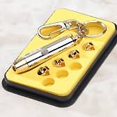 This is a simple description (some kind of engineering reversing :-)) of cheap KeyChain Lasers that are sold for 5 bucks or so.
THEORY
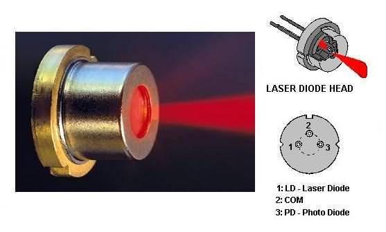
The basic circuit for powering a laser diode is as shown below in figure 1.
Most common
Laser Heads have inside two semiconductors: a
LD (
laser diode) and a
PD (
photodiode).
The
laser diode will be
forward biased and its cathode (
LDC) will connect to a driver transistor &/or network to regulate the LD current based on the photodiode current (feedback network).
The
photodiode will be
reverse biased, its anode (
PDA) will feed a driver regulator and thus the control will give a feedback signal for the LD driver.
Of course the feedback is an optical one, part of the laser beam goes backwards to reach the photodiode junction, as shown in figure 2.
According to Fig 2, the
laser diode head has three pins labeled:
LDC (Laser Diode Cathode),
PDA (Photo Diode Anode) and
COM+ (common Positive Terminal).
Inside the laser diode head we find the laser diode itself and a photodiode, used to regulate the laser diode current with an external feedback loop.
HARDWARE
Behind the
laser diode head there's tiny pcboard with SMD devices mounted on it (see figure 3).
SMD devices are shown in green; positive copper paths in red, negative in blue and interconnecting ones in black.
CIRCUIT
After careful examination I've came with the circuit schematic shown in Figure 4.