Use a Surplus Primestar Dish as an IEEE 802.11
Wireless Networking Antenna
Primestar was recently purchased by Direct TV who
is phasing out all the Primestar equipment. This means that the dishes are
being trashed, and are available for other uses such as the one I describe
here. It is easy to make a surplus Primestar dish into a highly directional
antenna for the very popular IEEE 802.11 wireless networking. The resulting
antenna has about 22 db of gain, and is fed with 50 ohm coaxial cable. Usually
LMR400 or 9913 low loss cable is used if the source is more than a few feet
from the antenna. The range using two of these antennas with a line of sight
path is around 10 miles at full bandwidth. I must stress the line of sight
part though. Leaves really attenuate the signal.
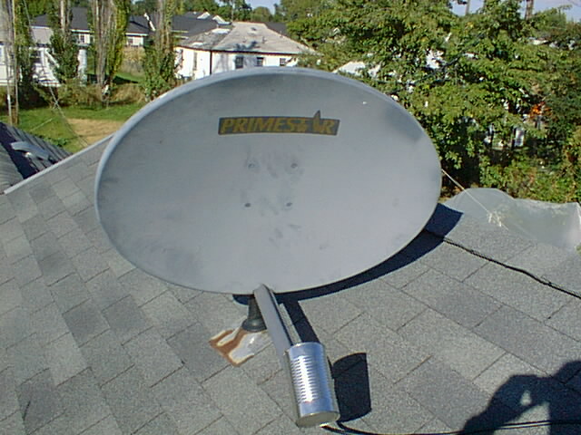 The dish in use with Apple's Airport.
Things You Will Need:
- A Primestar dish. (You may use any old
dish, but if it is bigger than the Primestar the gain will be higher, and
it may not be within the Federal Communications Commission rules for use within
the United States. In fact I have come to find out that there seem
to be several different dishes that Primestar used, and I am only sure that
the one I used, pictured above, used with the ordinary Wavelan or Airport
transceiver card is within the effective radiated power limits given by
the FCC.)
- A juice can (about 4 inches in diameter and
at least 8 inches long).
- A chassis mount N connector.
- You will also need a "pigtail" connector which
has the proprietary Lucent connector (for the PCMCIA card) on one end
and an N connector on the other. The pigtail can be obtained from a number
of online stores for $35 to $40.
Construction Steps:
- After deciding on a place to mount your antenna
(which hopefully has a line of sight path to the access point or other
IEEE 802.11 site), remove the apparatus at the feed position of the dish,
saving the mounting hardware.
- Using a can opener, cut one end of the juice
can out, drink the juice and wash it out
- Solder a quarter wavelength (1.15 inches) of
wire onto the center conductor of the chassis mount N connector.
- Using a punch or whatever other tools you deem
necessary, mount the N connector so that it is about 1.2 inches from the
closed end of the juice can as shown below. It is also a good idea to
put a drip hole at the lowest point of the can to insure that water doesn't
build up inside. After having this up a for a few months, I think it would
be nice to put a plastic lid on the open end of the can so that the inside
doesn't rust. During the time mine has been up, it has rusted and I have
lost a couple of db on the signal strength. These two things may be correlated.
- If you are certain of the polarization you
will need, mount the juice can so that that polarization is achieved.
(You want the antenna you are communicating with to be lined up with yours.)
If you don't know the polarization you can set everything up and before
mounting the juice can, experiment to get the maximum signal strength
by rotating the juice can around its axis. Most commercial antennas I've
seen are using vertical polarization, so that the picture below shows
you the proper orientation. You want to mount the juice can so that
the opening is just at the focus of the dish. In my installation I didn't
quite achieve this, but I only lost a db or two by taking the easy route.
I still have about 25 db signal to noise ratio, so this wasn't important
to me. The easy route is to mount the can as far back as you can along
the mount, by punching two holes through the can and bolting it in. The
perfectionist's method would be to find the best feed place (which I found
to be just a little farther back) and use some PVC tubing or something
to extend the mount so the feed is in the perfect position. In some installations,
every decibel will count and this should be considered.
.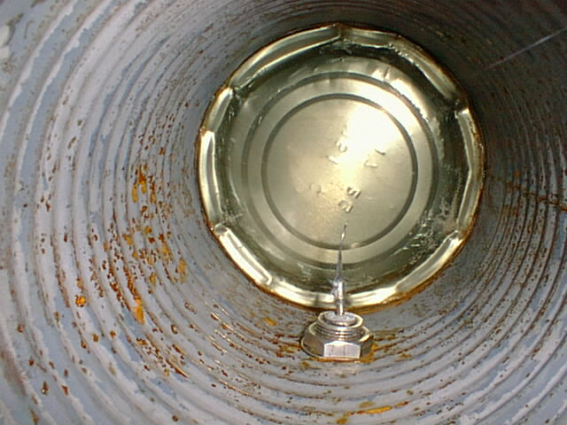 The inside of the feed can.
Some Considerations:
This antenna is very directional. You must have it
aligned very carefully, or you will lose a lot of signal. It also needs
to be mounted securely, so the wind won't be able to rotate it even a few
degrees.
This antenna is an offset fed dish, which means that
the feed horn (our juice can) is not positioned as much in the way of an
incoming signal, so it doesn't shadow the dish. This makes the aiming a bit
tricky, because it actually looks like it is aimed down when it is aimed
for the horizon. See the photo below of it aimed actually a few degrees above
the horizon. You can use the scale on the dish mount to determine the elevation
it is aimed at. The dish isn't as directional in the up/down directions
as it is side to side. This is fortunate, because without turning the mounting
upside down we can only get it set so it is a few degrees above the horizon.
I sacrificed a db of gain here by not turning it over, mostly because I'm
mounting it on a vent pipe, and didn't want to put that kind of wind load
on it. As mentioned above I don't really need the extra signal either.
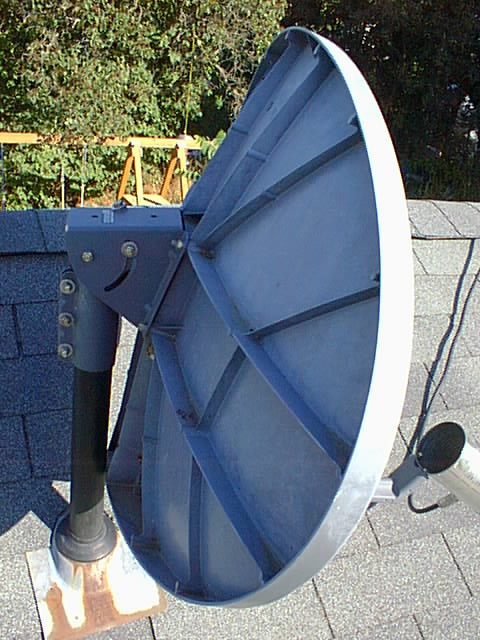 The mount of the dish. This photo also shows
the angle it must be tipped to be aimed at the horizon.
I believe this feed system could be improved by linking
two cans together (or using a section of pipe) to give the effect of lengthening
the length of the circular wave guide feed. This would further attenuate
undesired modes (other than the TE11 mode). The optimum length would be between
14 and 21 inches. The opening would still need to be at the focus of the
dish.
Use the Feed Can By Itself
You can use the feed can by itself as a cheap antenna.
It works as well as the commercially available "range extender" antenna,
but only in one direction, and it is so easy to construct!
Some More Photos
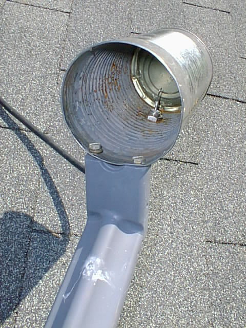 A photo of the mounting of the feed can.
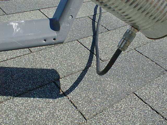 A photo of the coaxial connection to the feed
can.
Go to Rob's Airport Links.
Go back to
Rob's home page.


